Devices & connectivity

Make instruments
part of the same process.

Describe each device once, then use it across testing and maintenance. Keep connection settings, channel behaviour and simulated equipment understandable as the station grows.

Devices & connectivity

Your hardware.
One test platform.

Explore instrument families and integration paths. Select a brand, device family, category or interface to start your compatibility discussion.

Commands & drivers: SCPI · Modbus · ASCII · VISA · NI-DAQmx · DAQNavi. Interfaces and functions vary by model.

16 hardware families

*UVC approval applies to camera models confirmed by Raju Bros.

Brand families describe equipment to explore, not a tested-model list. A communication port alone does not establish compatibility. Required commands, response formats, adapters and licences must match your station.

Explore all device categories
Device category Typical use Integration path to check
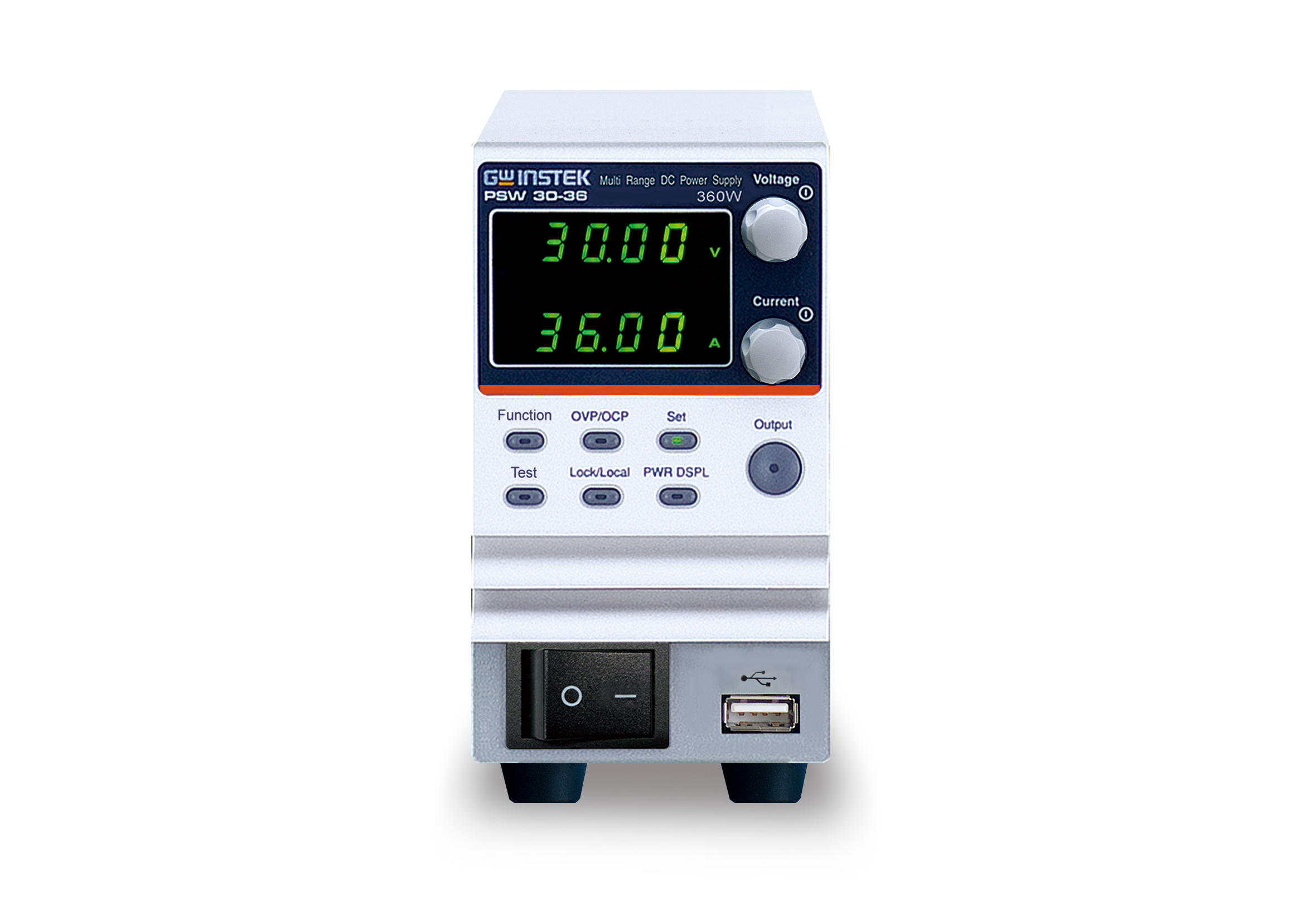
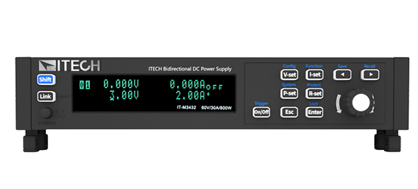
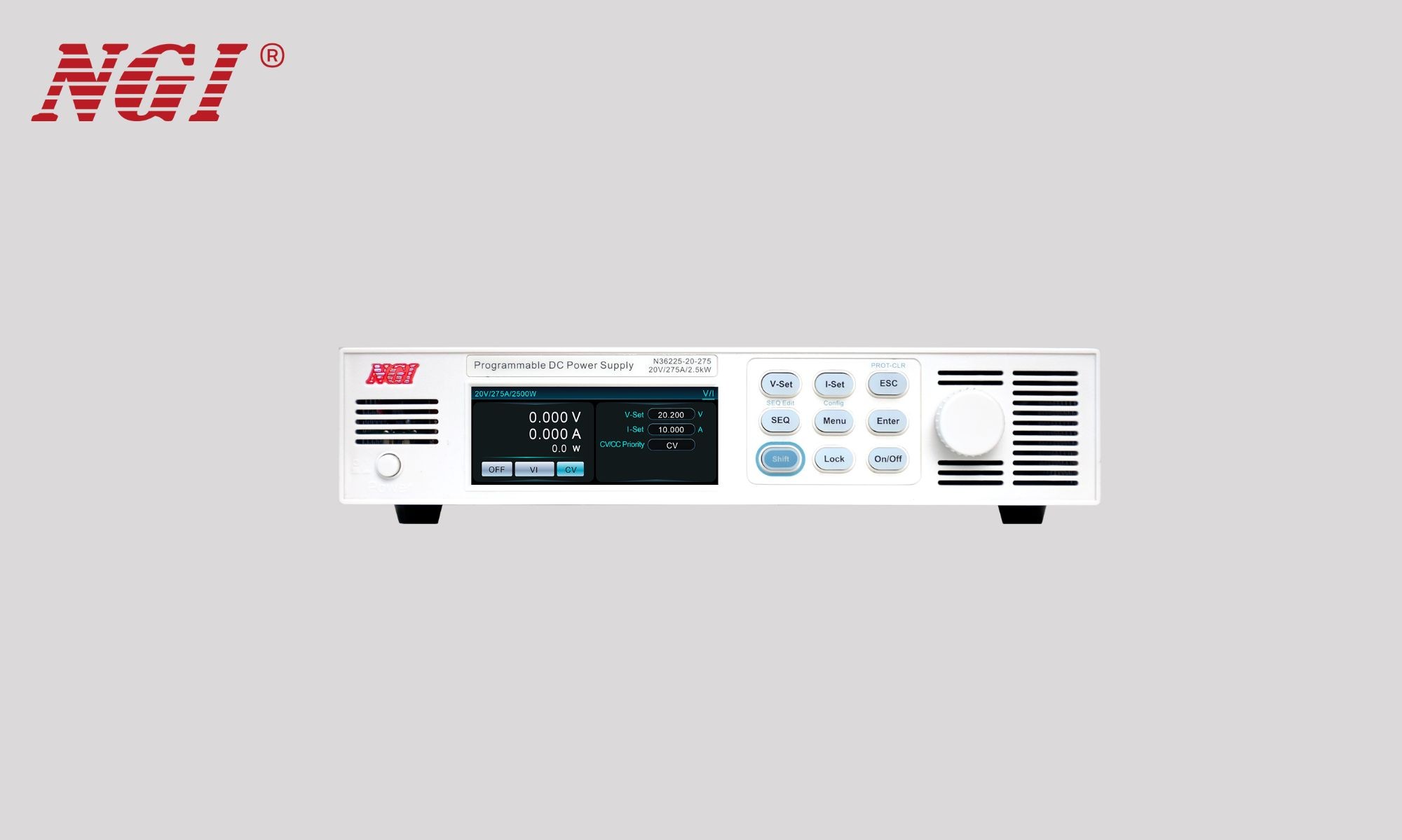
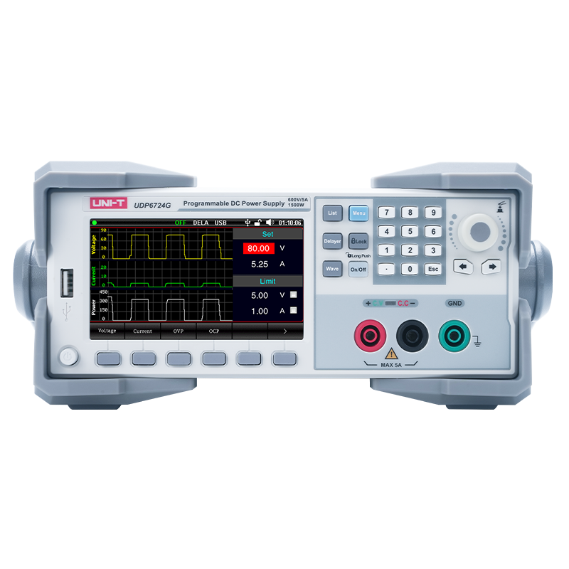
AC / DC power supplies Set supply conditions and read supported voltage/current responses. SCPI or documented instrument commands
Electronic loads Configure supported load modes and read measurements. SCPI or documented instrument commands
Battery simulators Configure the source behaviour provided by the instrument. Model-specific commands
Source-measure units Combine sourcing and measurement where the command path is supported. Model-specific commands / VISA
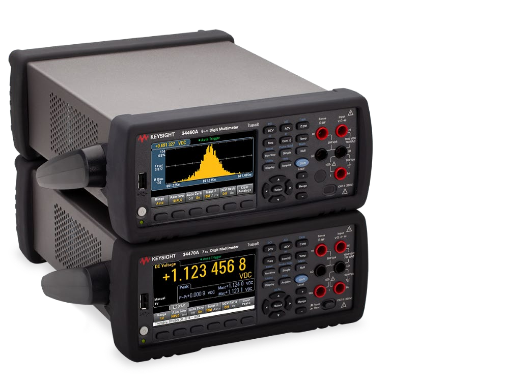
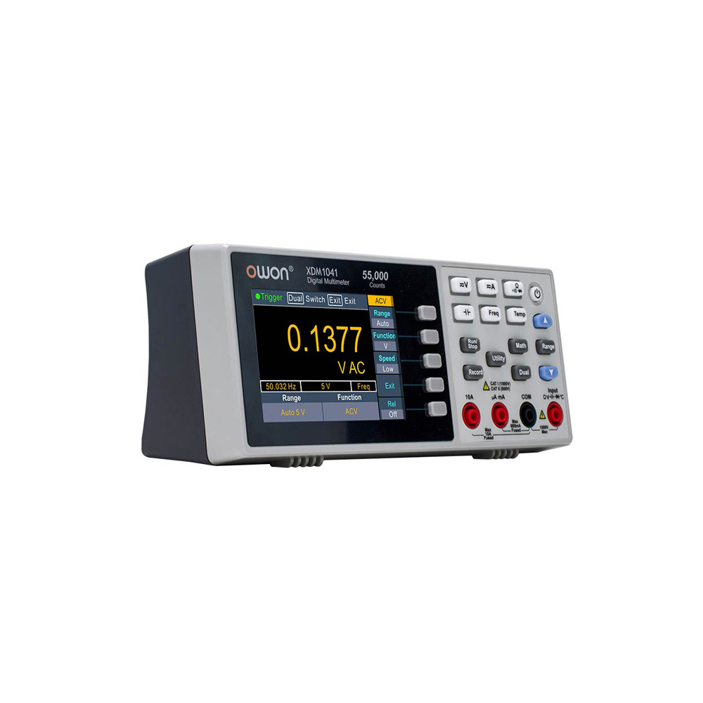
Digital multimeters Read voltage, current, resistance and other supported measurements. SCPI / serial / VISA
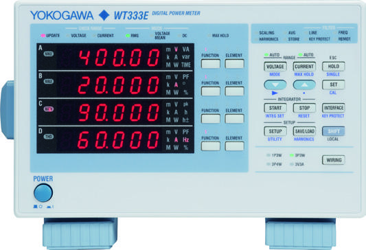
Power & energy meters Read power, energy and electrical performance values. Instrument commands / supported Modbus mapping
Oscilloscopes Request supported scalar measurements; waveform transfers require separate review. Model-specific SCPI / VISA
Signal & waveform generators Configure supported signal output parameters. Model-specific SCPI / VISA
RF & spectrum instruments Review the exact remote measurements required by the application. Model-specific commands; integration review
LCR & component meters Read supported component measurement values. Documented command and response formats
Electrical safety testers Review instrument control, interlocks and result retrieval for the station. Model-specific integration and safety review
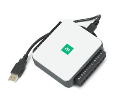
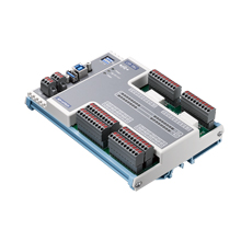
DAQ / UDAQ & analog / digital I/O Bind supported channels for acquisition and output control. NI-DAQmx / DAQNavi / supported device protocol
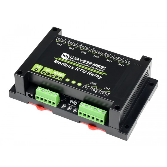
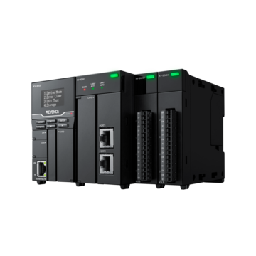
Relays & PLCs Switch supported outputs and exchange mapped station signals. Modbus RTU / TCP / documented commands
Temperature controllers Exchange supported setpoints and process readings. Supported Modbus mapping / serial commands
LED & optical instruments Use supported optical checks and instrument response formats. FEASA integration / model-specific protocol
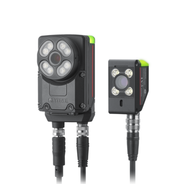
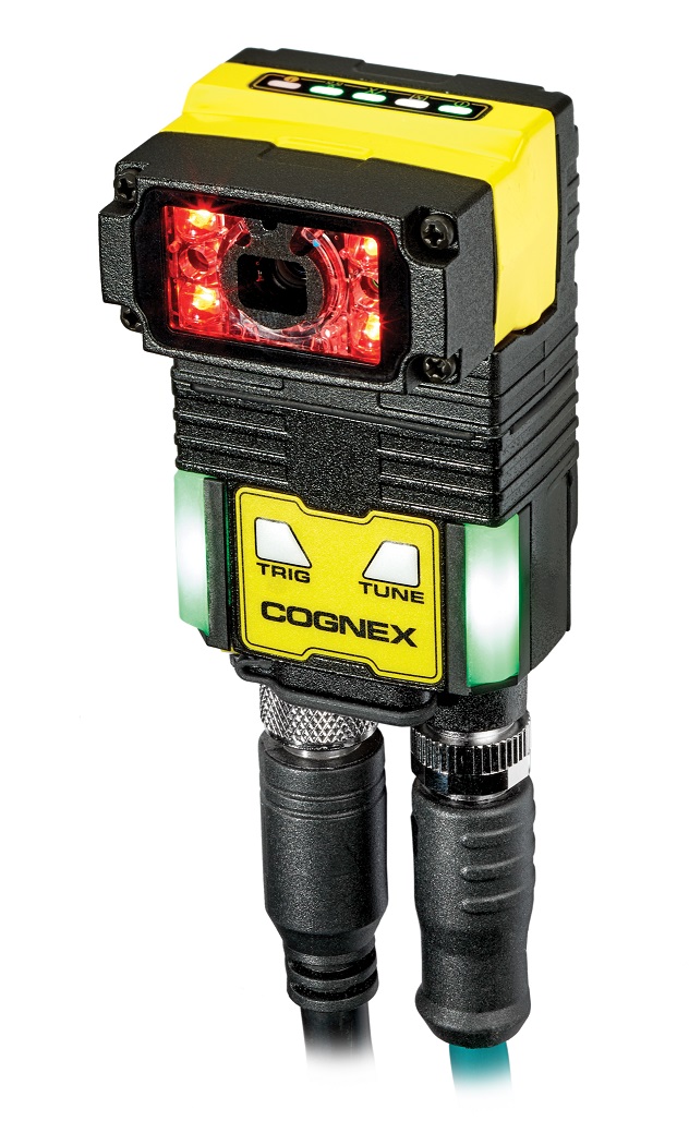
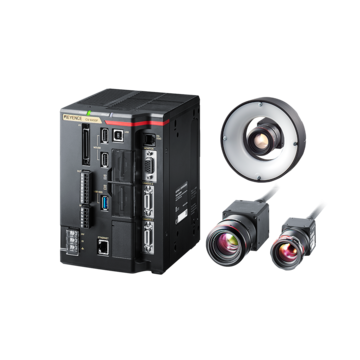
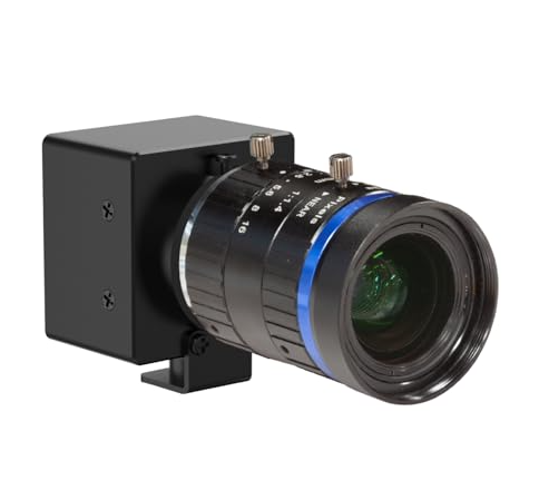
Cameras & thermal cameras Configure supported acquisition, inspection triggers and result exchange. UVC / supported camera SDK / model-specific serial or LAN / thermal adapter
CAN / CAN FD / LIN interfaces Exchange bus frames using supported adapters and licensed workflows. CAN / CAN FD / LIN
Barcode scanners Capture barcode identity through the configured input route. Keyboard input / supported serial capture
Label printers Send configured labels through the supported output route. Printer driver / printer commands
Serial & custom instruments Configure commands, framing, replies, timeouts and result interpretation. ASCII / HEX / supported TCP or serial protocol
RS485 / Modbus devices Exchange configured relay, I/O, meter and controller values. Modbus RTU register map / documented RS485 command protocol

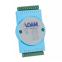
Product images: manufacturers’ product pages and published collateral. Brand names belong to their respective owners; their appearance does not imply endorsement.

Device Configuration holds a name, category, role, description, brand/model information and connection settings for each instrument. A sequence refers to the configured device, so the station can contain several meters, supplies or interfaces with distinct responsibilities.

Device configuration Inside the software
Actual application capture · COM / Serial setup for a new device, before instrument details are entered.

Illustrative example · A station with two meters

One named meter measures supply current; another measures an output voltage. Each has its own connection and command settings. A sequence step selects the relevant device rather than assuming that every station has the same instrument on a fixed port.

Enable or disable devices deliberately and use connection feedback when commissioning. Entering a brand and model identifies the equipment; it does not install a driver or establish compatibility by itself.

Connection family Configuration and dependencies
Serial / RS485 COM settings, baud rate, data bits, parity, stop bits, framing, response timeout and the device command format.
LAN / TCP and Modbus Address, port and protocol-specific settings, including the appropriate register or command interpretation.
SCPI / GPIB / VISA The instrument command set and supported resource/addressing path, with the required vendor runtime.
CAN / CAN FD / LIN A supported adapter, channel and bus configuration, plus the relevant specialist licence.
DAQ / UDAQ Supported hardware and channel bindings; vendor drivers are required where the selected integration uses them.
Cameras and printers A compatible SDK, driver or output route and the configuration for the chosen inspection or label workflow.

Custom command formats and response handling help adapt supported connections to the documented instrument protocol. Confirm the exact brand, model, adapter and driver version with the team; an interface family is not a universal driver for every instrument.

Windows may assign a new COM number after an adapter is reconnected. Supported USB identity matching uses available VID/PID, serial number and hardware information to locate the device’s current port. The saved port can be a fallback.

  1. Capture the intended adapter

    Select the connected serial device and save its available identity with the communication settings.

  2. Check reconnection

    Reconnect the adapter and confirm that the intended instrument is found at its current COM port.

  3. Resolve ambiguous identities

    Review adapters that share an identity or have no unique serial number before depending on automatic selection.

A stable USB identity solves port discovery. Baud rate, protocol, cable wiring and whether another program holds the port still affect communication.

Supported DAQ integrations, including NI-DAQmx and Advantech paths, connect channel configuration with acquisition and output operations. Discovering hardware is followed by an explicit binding to the channels required by the station.

Live inputs

Set the supported input type, acquisition behaviour, scaling, calibration, debounce and per-channel display precision. Review raw and interpreted values against a known input.

Output controls

Prepare named controls for selected outputs. Use the available ARM/DISARM, all-off and automatic disarm behaviour during permitted maintenance work.

Commanded output state and measured feedback answer different questions. Where confirmation matters, read a suitable feedback channel rather than assuming a successful command proves the physical output.

NI-DAQmx integration requires the matching native NI driver on the station. Ordinary relay and DAQ operation is separate from the specialist UDAQ firmware programming capability.

The Virtual Machine workspace manages simulation profiles that can be launched, stopped or disabled. Launched profiles participate in the normal device workflow with simulated responses, allowing engineers to exercise configured logic while physical equipment is unavailable.

Illustrative example · Prepare the logic before the bench

Use a simulated reply to review response decoding, formulas and result handling. Keep that evidence identified as simulation, then repeat the acceptance checks with the actual instrument and product. A virtual pass does not establish physical measurement accuracy or fixture behaviour.

  1. Install and identify

    Prepare vendor drivers, the correct physical interface and the device’s documented settings.

  2. Connect and inspect

    Use Test Connection and Communication Studio to inspect a supported identification query or other appropriate command.

  3. Verify the measurement

    Check framing, decoded values, units, scale and response timing against a known condition.

  4. Validate the production use

    Map the device into the sequence and test normal, disconnected and unexpected-response behaviour.

Check your instrument compatibility.

Share the exact brands, models, interfaces and vendor drivers you intend to use.

Review your device list

BHARAT TEST SUITE · Application screen